12. Mspec0

| |
12. Mspec0 |
 |
12.1 Input Panel
The area "Antenna Control" inside the Mspec0 input panel shows the Field System settings (see Chap. 11) and allows one to choose between the two interface modes :
- AUTOMATIC : the interface controls the pointing and the receiver settings (the parameters set before through the Field System are ignored)
- MANUAL : the telescopes is already pointed on-source, the parameters set before are kept and the interface controls the spectrometer only.

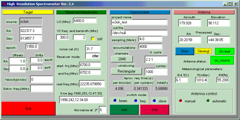
Fig. 12.1 : Mspec0, input panel
The input panel is divided into four sections :
|
Target |
In AUTOMATIC mode it is possibile to set the source coordinates. The source velocity (km/s) is only a post-processing reduction information (the interface at the moment does not apply any redshift correction, even if the panel is already arranged for this).
In MANUAL mode the panel shows the parameters set by the Field System.
|
Observed Frequencies |
In AUTOMATIC mode it is possible to change the receiver parameters in this panel :
- LO (MHz) : local oscillator frequency (see the single sections related to the receivers)
- VC freq and bandwidth : starting frequency and bandwidth of the videoconverter (typically the vc07) coupled to the Mspec0. Fig. 11.1 shows an example with a 300÷302 MHz bandwidth. The SET box must be checked.
- Noise cal. : temperature of the noise calibrator (listed, for all the frequencies, in the receiver calibration file or, alternatively, obtainable from the Field System as default value through the command caltemp=vn)
- Receiver mode : receiver label
- Start/End frq : parameters of the graph axis (output panel)
- Rest frq : rest frequency of the emitted line (post-processing reduction information)
- Time : time, reduction information
- Normalize at 2° : parameter useful in bin overflow case (increasing the value the signal power diminishes and channel saturation can be avoided; the default value is 6)
In MANUAL mode the panel shows the parameters set by the Field System.
|
Spectrometer |
- Project name : name of the project (optional), there must be no empty spaces
- Out file : output file position, usually /data/filename.obs. A post-processing software , which delivers FITS format, is available.
- Sampling rate : twice the set bandwidth as default.
- Accumulations : number of accumulations that forms a spectral block (must be < 65500)
- Channels : spectral channels number
- Duty cycle : On-Off-Cal format where On is the number of On pointings (2 in fig. 11.1), Off is the number of Offset pointings (2 in fig. 11.1) and Cal is the number of pointings necessary for the signal calibration (1 in fig. 11.1).
- Windowing: spectrum display mode, Rectangular as default (possibilities are also Hamming, Hanning, Blackman-Harris, Kaiser-Bessel)
- Cycles : number of desired cycles
- Approx. req. time : per block (required time for the processing of 1 block), per cycle (required time fo a cycle On, Off, Cal), total (number of cycles x cycle time). The antenna slewing time is not included.
- Switch mode : "beam" as default (position switching). The frequency switching mode is still under development and the slave mode is not of astronomic interest.
- Start : start the acquisition (nearly 20 seconds are required)
- Stop : stop the data acquisition. ALWAYS STOP THE ACQUISITION BEFORE DOING ANY CHANGE OF THE PARAMETERS.
- Quit : close the interface panel. It is strongly recommended to close the panel only at the end of the observing session.
|
Antenna |
This section is dedicated to the antenna status monitoring.
![]()