| |
8. Back End |
 |
8.2 Continuum
8.2.1 Analog Total Power Backend (2-GHz bandwidth)
The backend is formed by 4
printed circuit boards, also including a digital part for board
control and setup, and 4 voltage-to-frequency converters to
digitise the detected signals. The digitised samples are sent to
the acquisition computer by means of a LAN (Local Area Network).
Each board is designed to have three inputs, so that it can be
connected to different receivers.
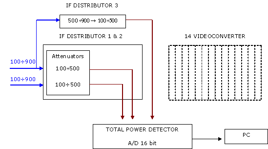
The backend architecture is such that each input, before
detection, is available at two backend outputs. This allows the
system to simultaneously send every receiver output to another
backend, for instance a FPGA backend (e.g. for spectroscopy or
VLBI observations), or to a remote detector (this last chain is
specifically optimised in dynamics for a fibre optic link).
Prior to the detection, the signal goes through:
- a variable attenuator, to set the signal power level in
a suitable range;
- a filter bank, to reduce the bandwidth if
necessary.
All these characteristics make this system both a data
acquisition machine and a signal distributor.
The control stage of the acquisition system, realised by a small
Linux computer with an embedded FPGA board, allows the control
system to remotely set up the equaliser, the attenuation values,
the filter bandwidth and the sample rate of the acquisition.
The sampling signal can also control the switching of a noise
source of known temperature, which is injected through the
receiver chains, so that the gain variation of the receivers can
be tracked and compensated during the post processing phase.
The main specifications of this backend can be summarised as
follows:
14 x 3 IF inputs in the range 0.1 - 2.1 GHz;
2 IF outputs in the range 0.1 - 2.1 GHz;
selectable bandwidths: 230, 725, 1200, 2000 MHz;
0 - 15 dB variable attenuators, configurable with 1 dB
step;
up to 21 bit resolution;
automatic cancellation of output offset;
noise source chopping frequency: 0.5 - 500 Hz.
The backend dynamical range varies with the data sampling
interval.
Rule-of-thumb formulas, specific to this backend, to compute the
available bits and the dynamical range in dB are:
n_bit = fix(ln(1800*t)/ln(2))-2
n_dB = 20 * log10(1800*t)
where t is the sampling interval in milliseconds (minimum value
is 1 ms).
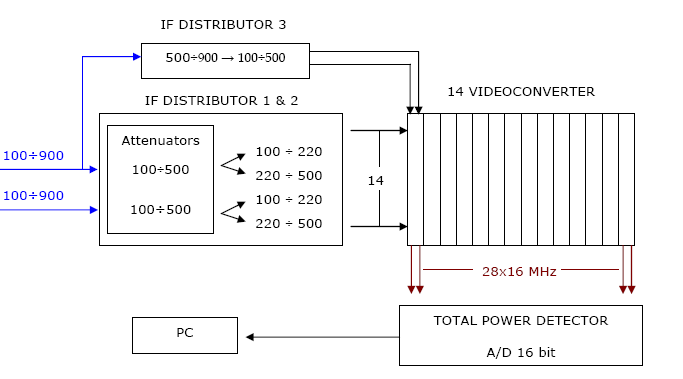
The terminal is made of two parts: IF distributor (receives the input from the Front End and splits them in sub-bands), Videoconverters (14 units that operate the base-band conversion and the integration). It is possible to choose between two outputs :
A) 28 narrow bands : minimum width 0.125 MHz, maximum 16 MHz*, central frequency user-defined (maximum total bandwidth 400 MHz).

Fig. 8.3 : Maximum bandwidths (MHz) processed by the Mark IV, example at 22 GHz
* 0.125 MHz and 1 MHz band are available only with external filter, please ask if available at the site.
B) Processing of the whole input: 2x400 MHz centered at 300 MHz and 1x400 MHz centered at 700 MHz

Fig. 8.4 : Maximum total bandwidths (MHz), example at 22 GHz
At 1.4, 1.6, 2.3 GHz available bandwidths may be considered less then what is reported because of interferences.
![]()