BEST - 2
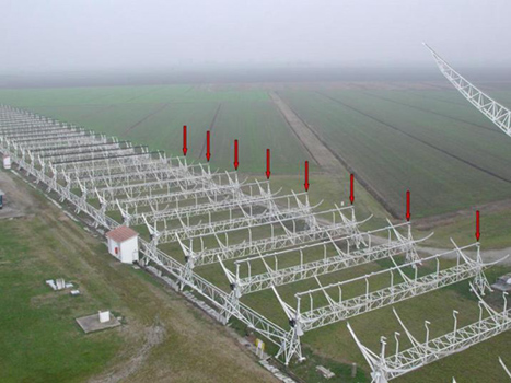
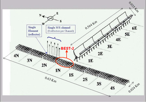
BEST-2 was the second phase of the BEST project and it provided the installation of 32 receivers in a N-S channel of the Northern Cross Antenna. Every channel is composed by 8 cylindrical-parabolic antennas where 4 receivers were installed (8 antennas x 4 receivers = 32 receivers). The working bandwidth is 400-416 MHz and the overall geometrical area is 1410 square meters.
 |
 |
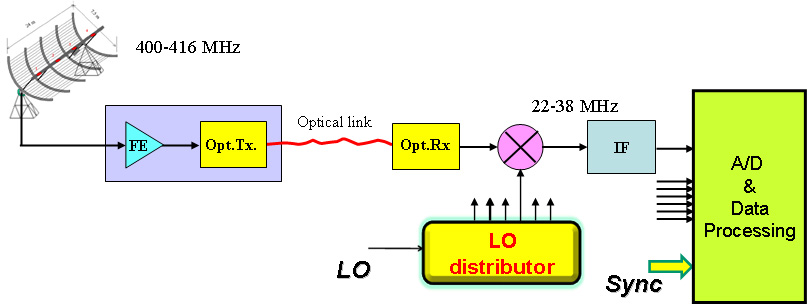
Picture below shows the block diagram of the BEST-2 system.
 |
||
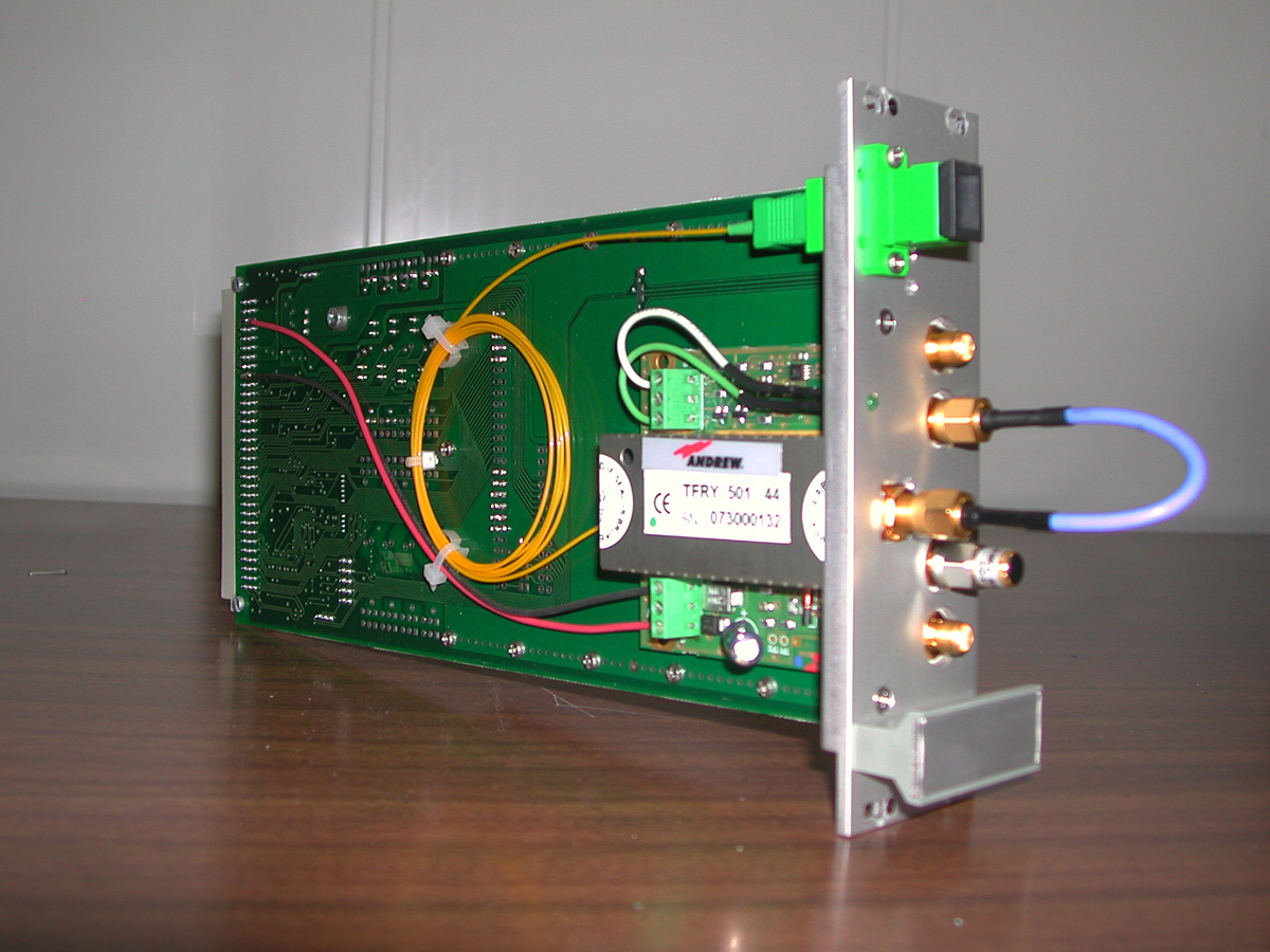
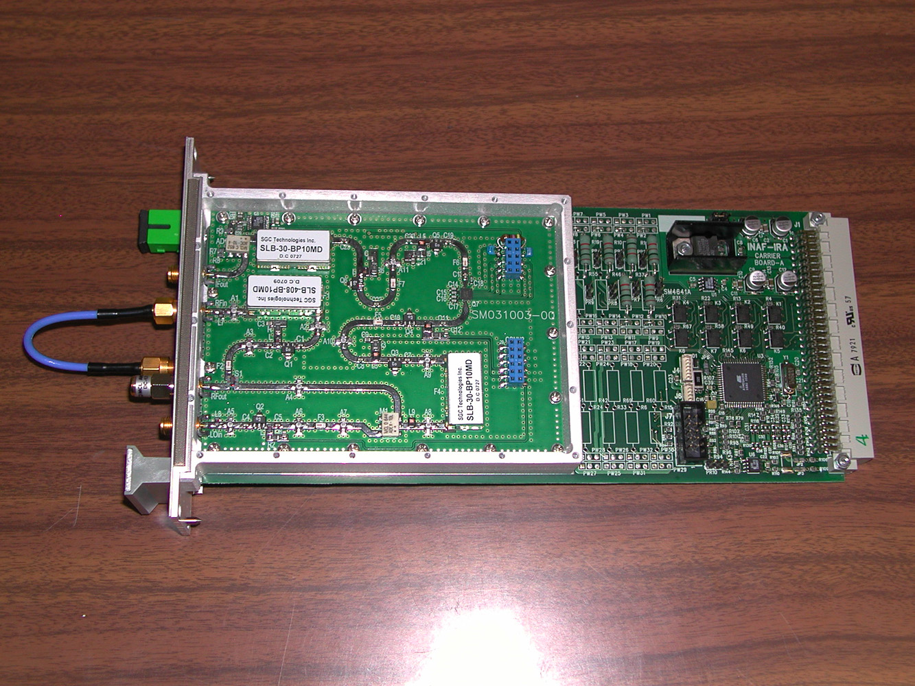
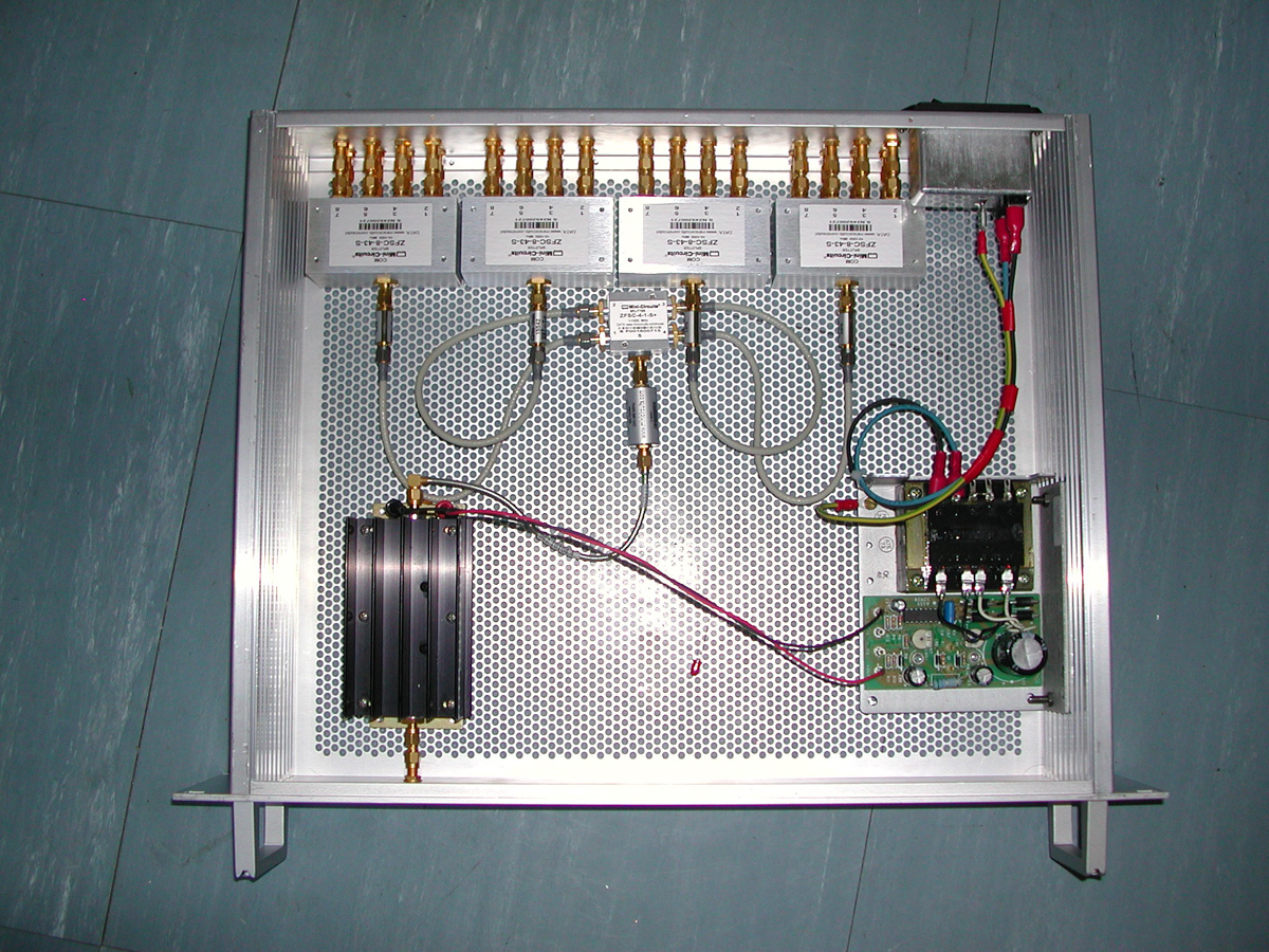
The signal received from the antenna (16MHz@408MHz) is amplified and filtered by a Low Noise Amplifier followed by other 2 amplifier stages. This block realize the front-end (FE) and its box is placed on the antenna focal line. Then the analogue signal is transmitted to the processing room via optical fiber, of course a diode-laser provide to convert the electrical signal in optical. A micro-controlled IF board (Intermediate Frequency) placed in the receiver room, translates and adapts the signal for the back-end system. The signal is down-mixed at IF=30MHz. Electronics attenuators are inserted along the receiver chains to equalize the gains. Since the back-end is shared between the BEST-2 and BEST-3lo system, an analogue switch providing to select the correct inputs.
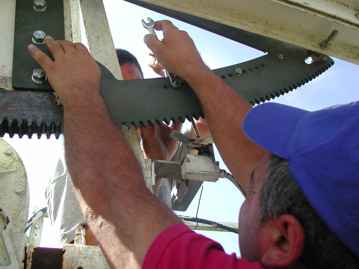
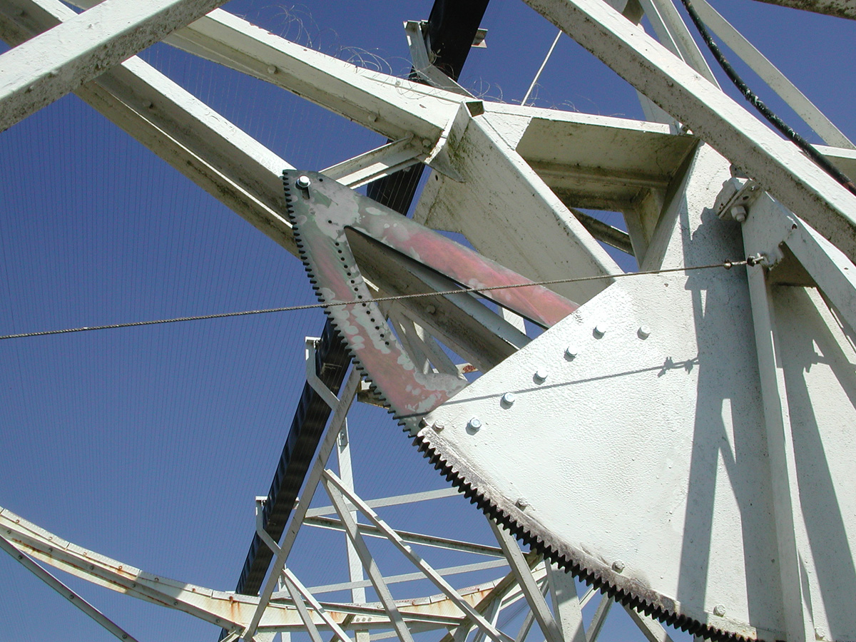
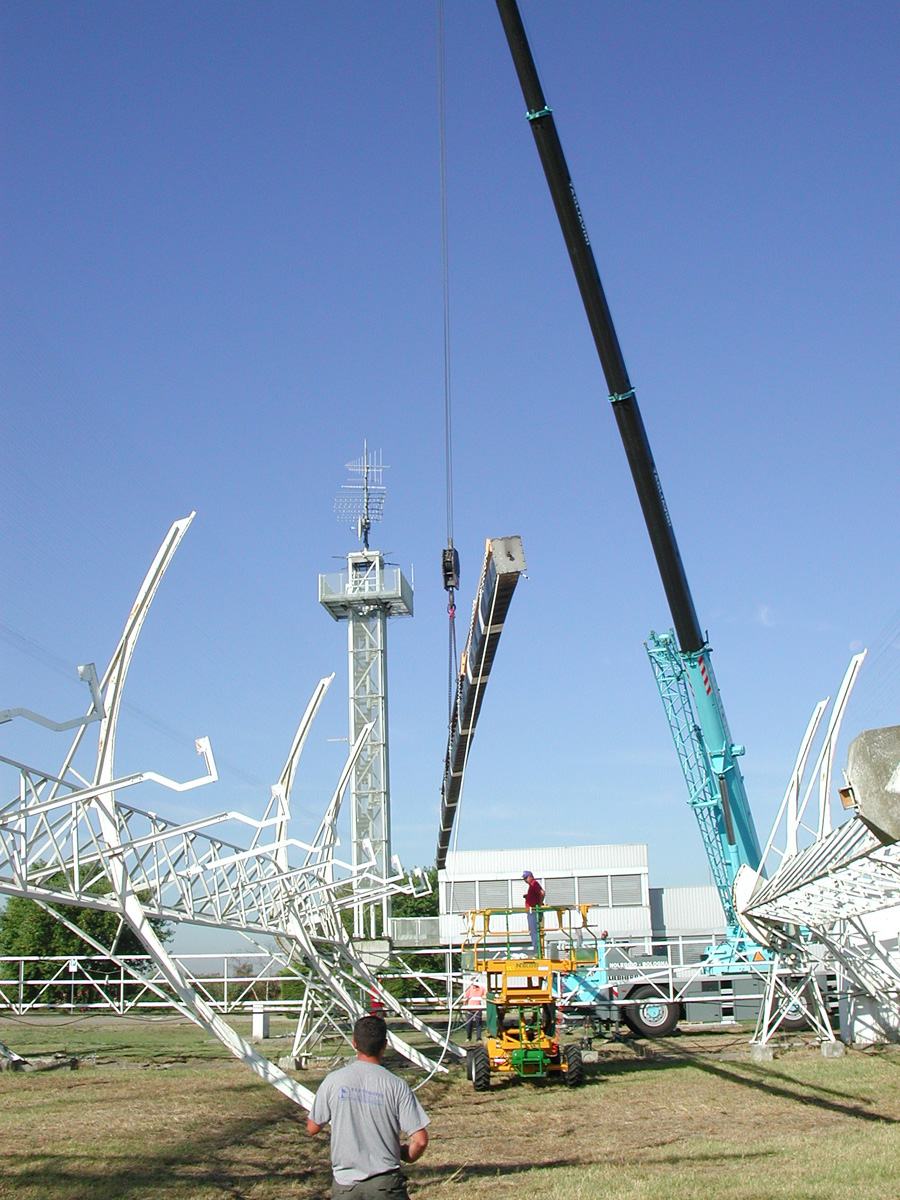
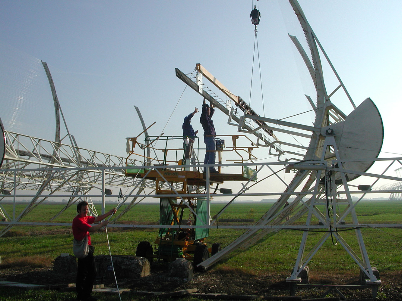
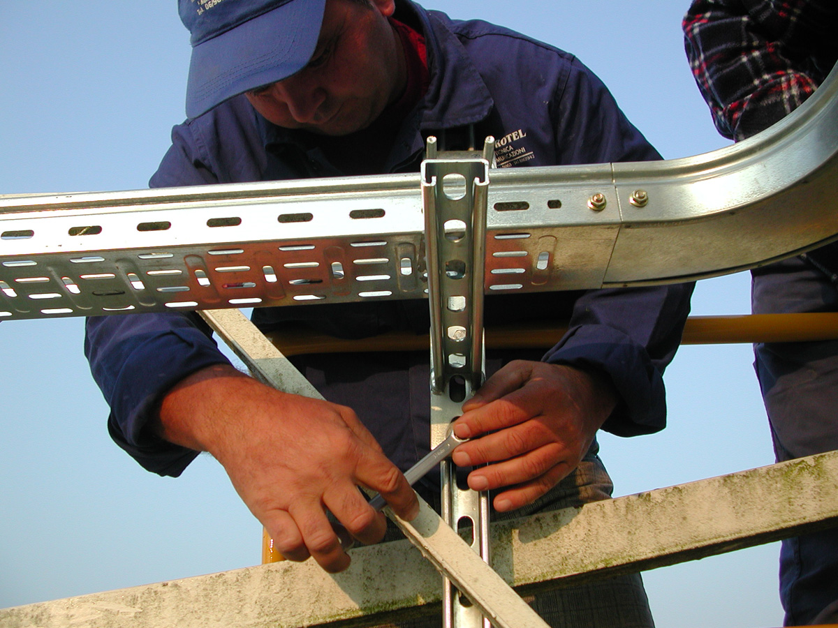
Before the installation of the front-end, some mechanical modifications for every N-S cylindrical-parabolic antenna were done, in order to easily install the electronics on the focal line. The main modification were performed in 3 steps:
- Modification of the steering system. This step was necessary
in order to increase the maximum course in North direction of the antennas
and to simplify the maintenance and all the operations over the focal
lines.
 |
 |
 |
 |
 |
 |
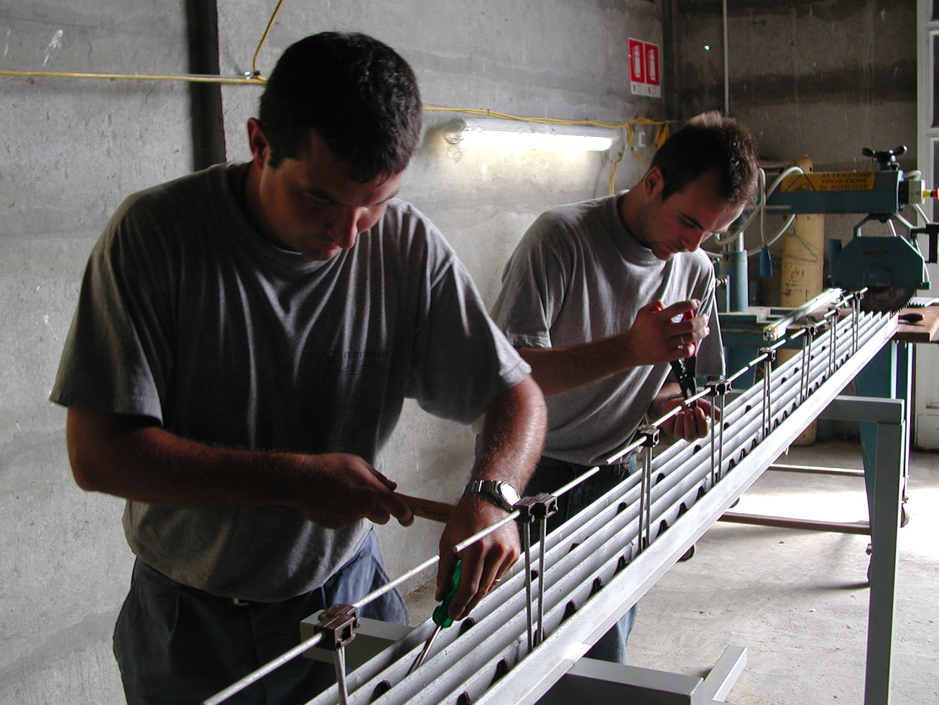
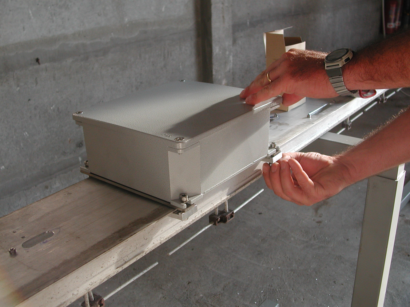
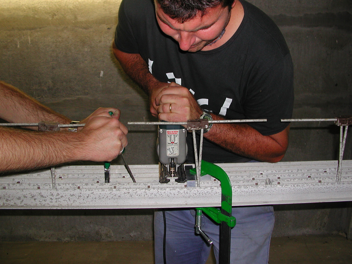
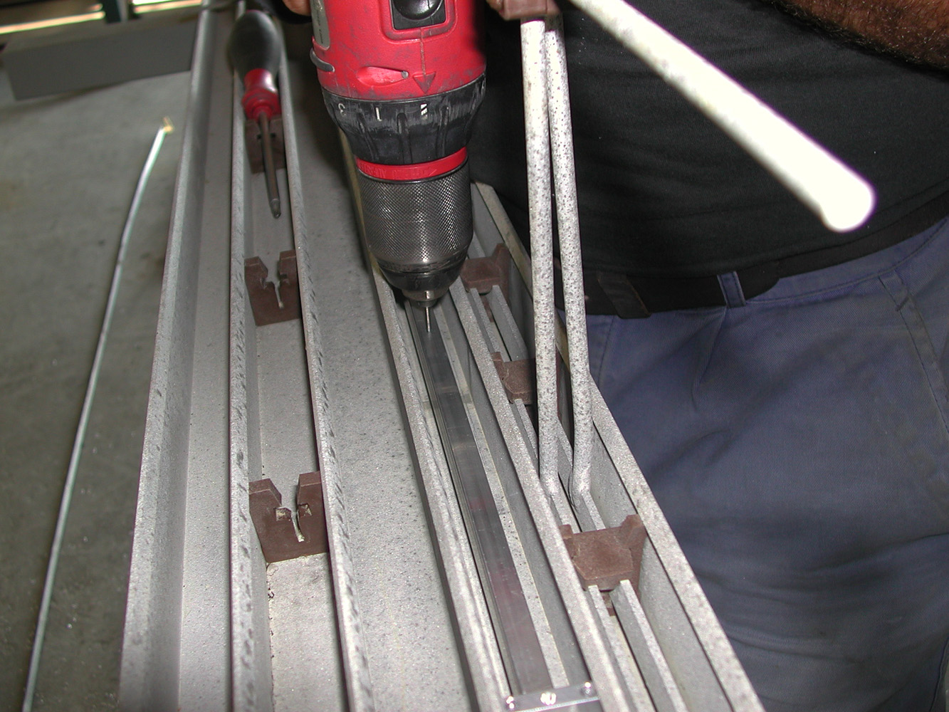
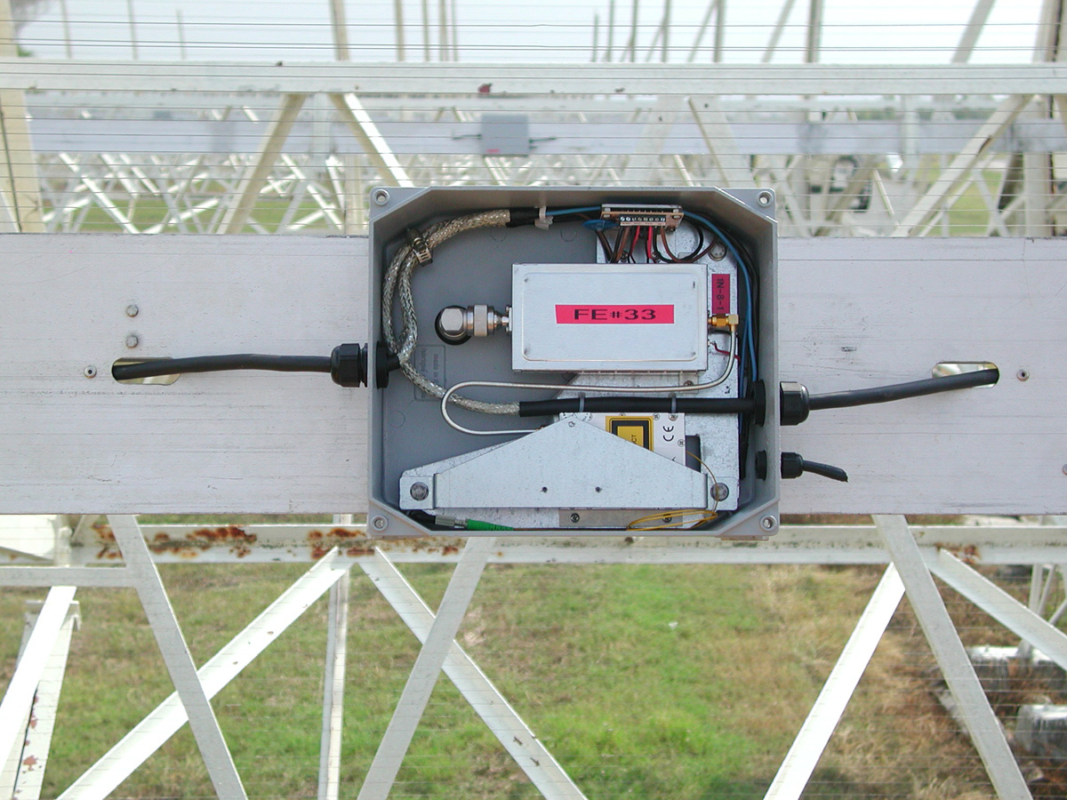
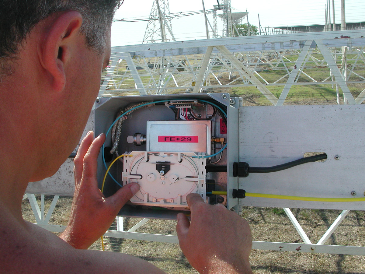
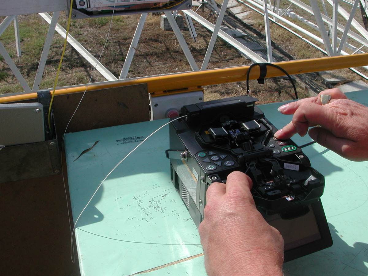
- Structural modifications of the focal line. This steps consisted removing the "Christmas tree" structure and cutting every single line after the balun and matching the snippets with impedance adapters. Then via waterproof connectors, the signals is fed into the waterproof boxes positioned on the focal line. All FEs and optical TXs are inside the boxes.
 |
 |
|||||||
 |
 |
 |
||||||
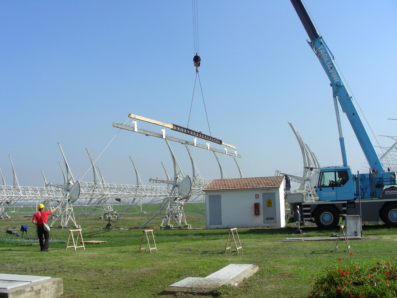
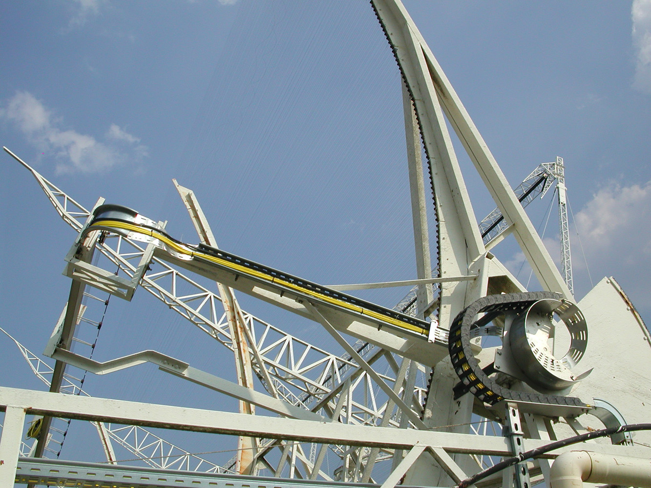
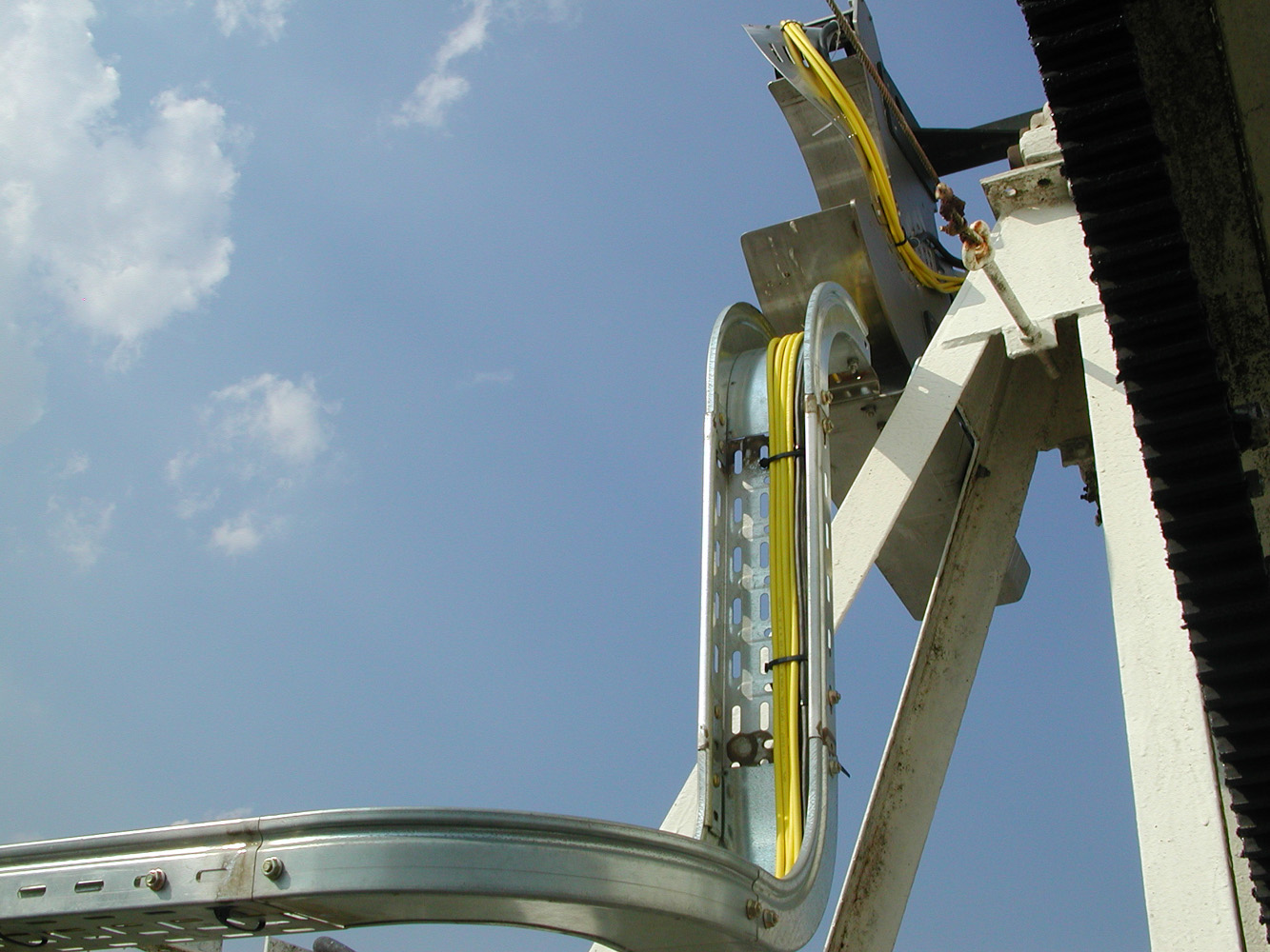
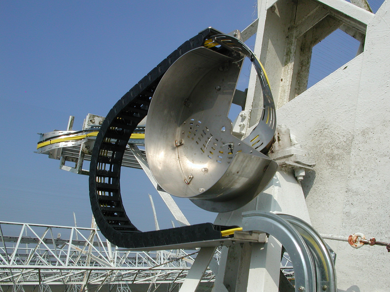
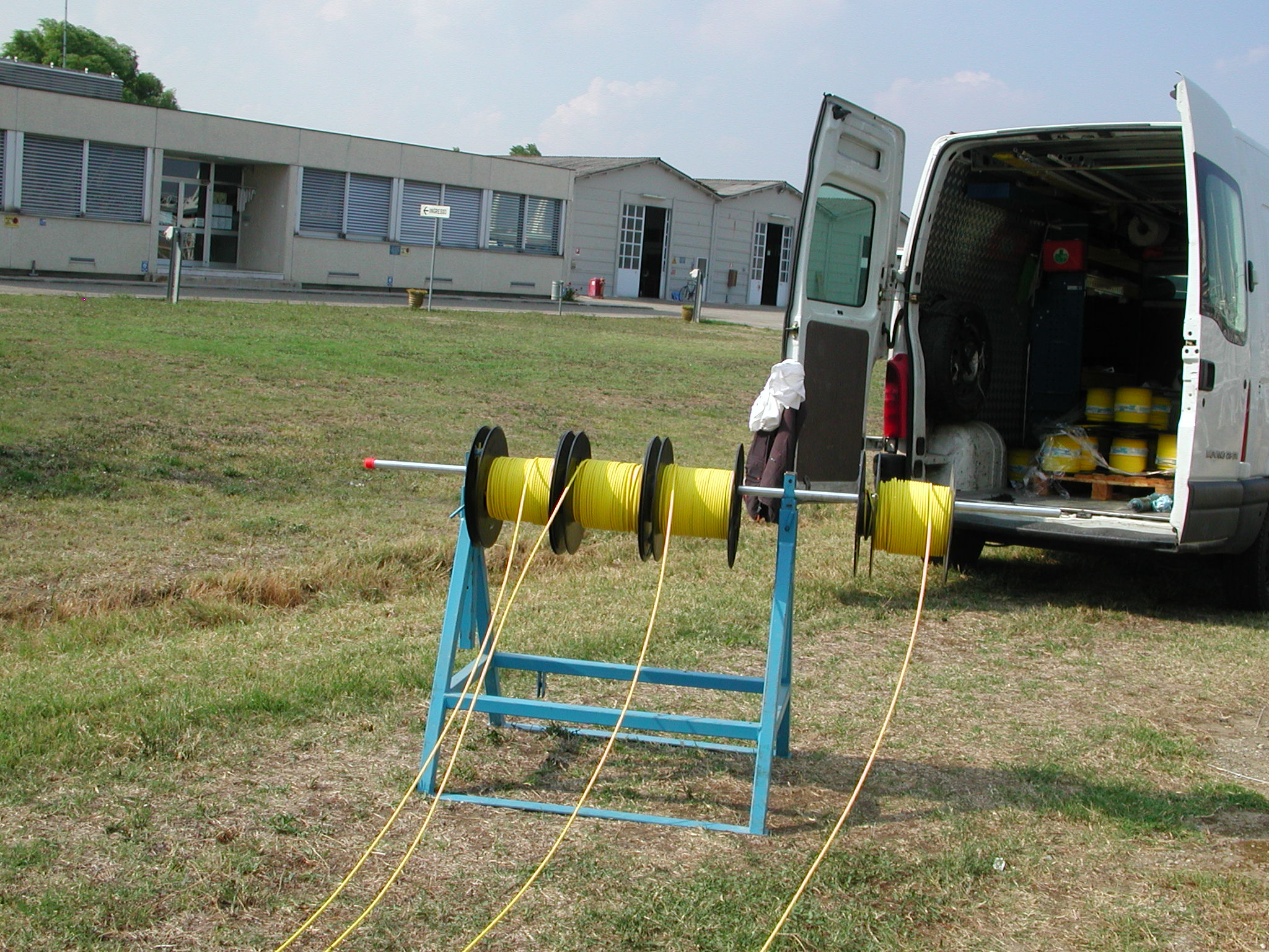
- Analog optic fiber links & copper wires cabling predisposition.
To avoid suffering flexes, tight bends or torsions that might compromise
the functionality of the TX system, a guide were built to lead the cables
from the boxes into the cabinets.
 |
 |
 |
 |
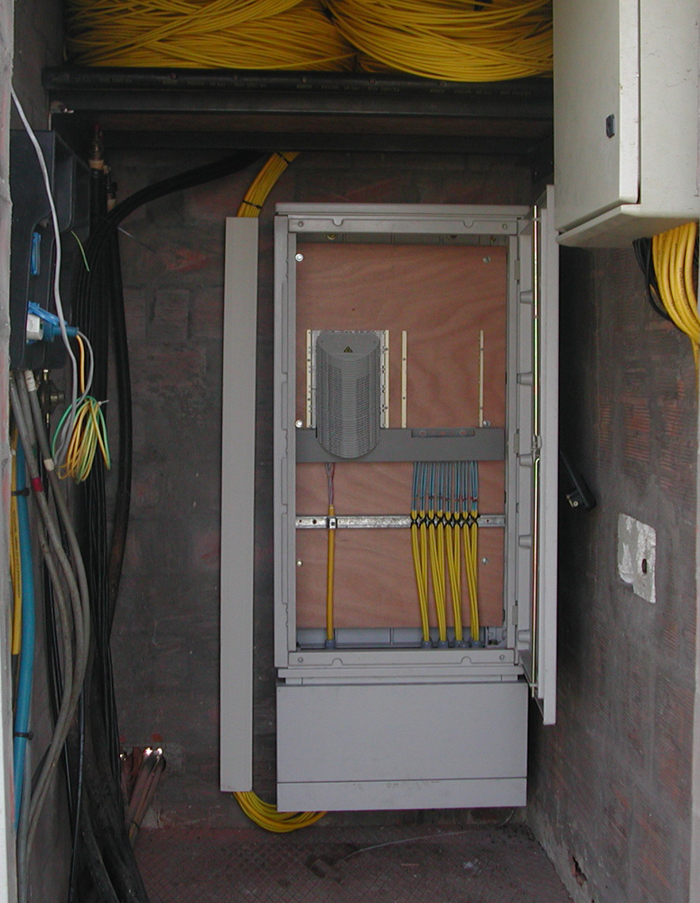 |
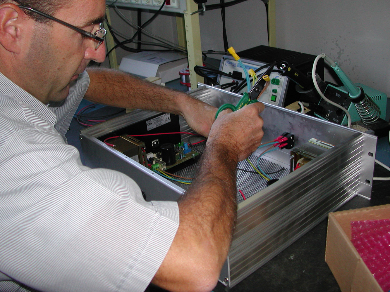
After the mechanical modifications all the 32 FEs, lasers and analog optical fibers were installed to transmit the analog signal up to the receiver room. The maximum length of the optical fiber link is 700 mt. To supply the electronics inside the boxes, DC linear power supplies were used and installed within the cabinets.
 |
 |
 |
 |
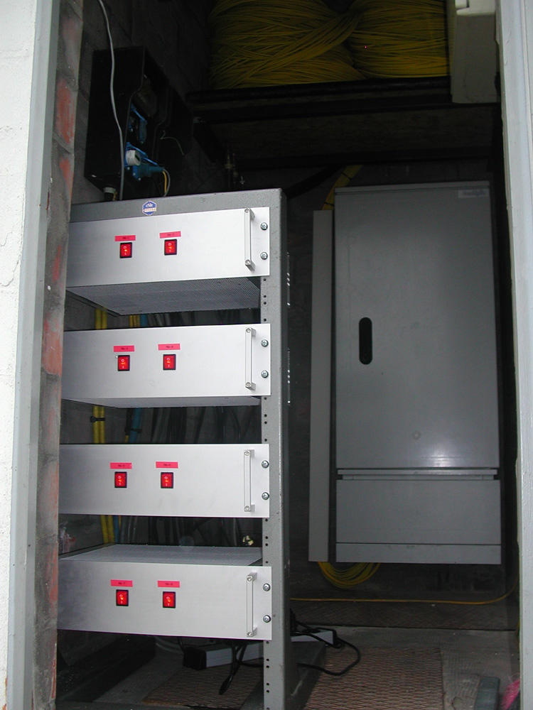 |
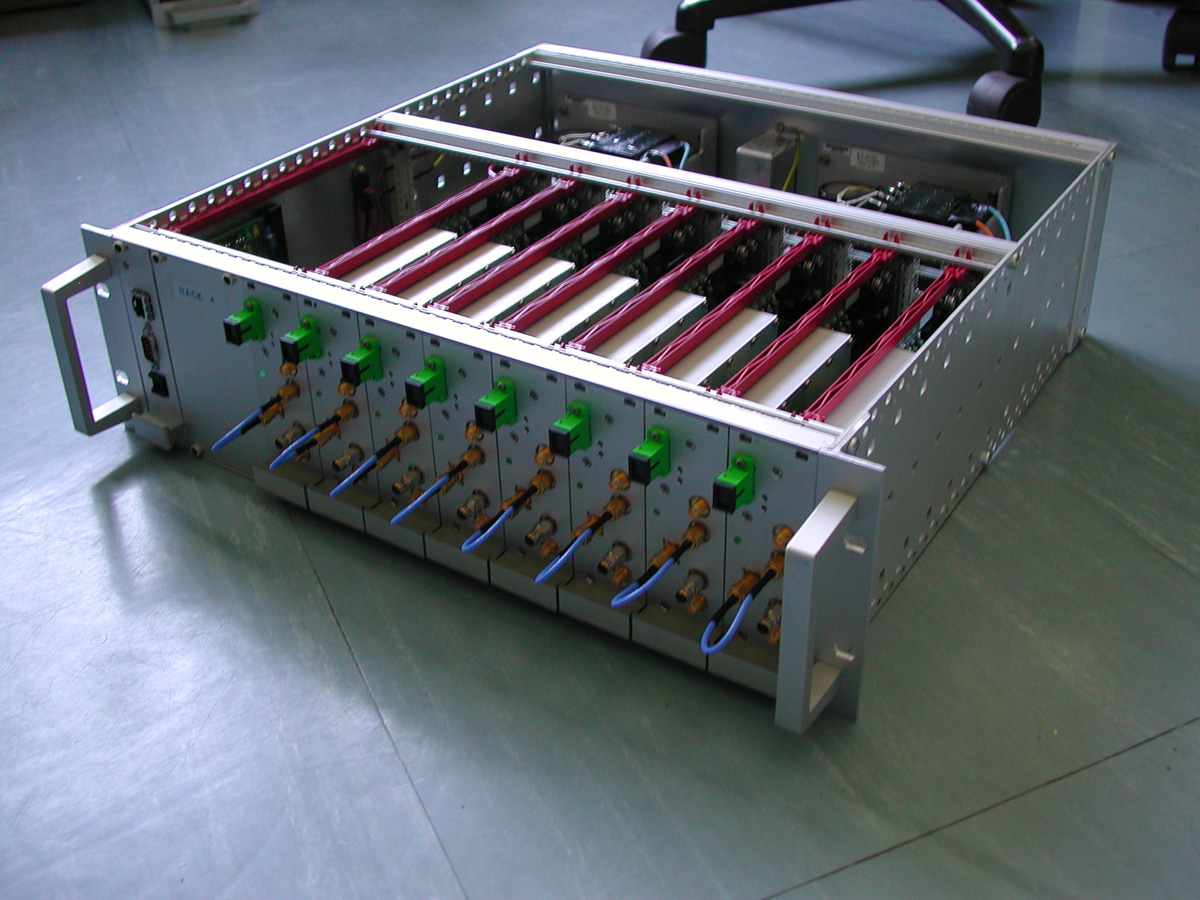
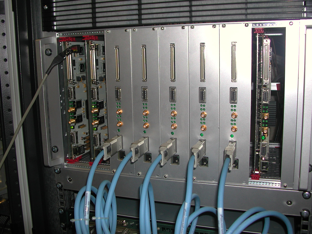
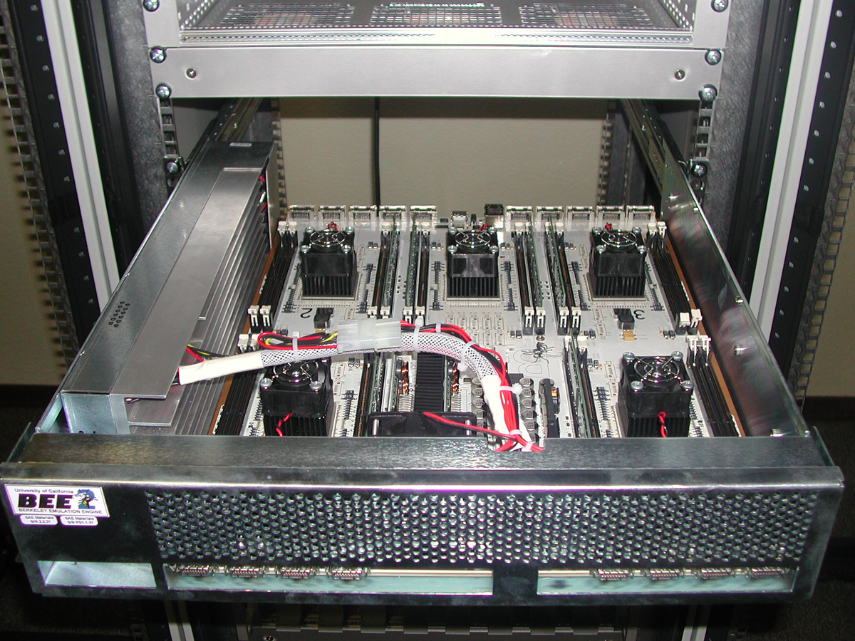
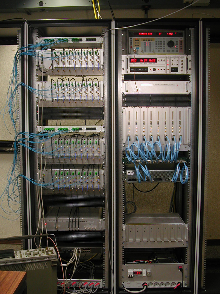
Inside the receiver room optical RXs, IF frequency circuitry, LO and clock distributor, ADC boards and BEE2 back-end system were installed. All the optical and coaxial paths were equalized in order to have the same delay. Moreover, thanks to a digital micro-controlled attenuator inside the IF circuitry, it is possible to tune the gain of the chain. All the commands to set the micro-controllers, come via LAN.
 |
 |
 |
 |
 |
 |
 |
 |
 |
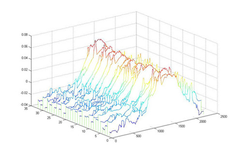
The first signal coming from Cassiopea-A were acquired by the system described above. In the figures below the radio-source transit can be observed. The graphs represent the power variation (in time) of the 32 BEST-2 receivers.
 |
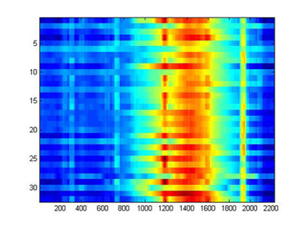 |
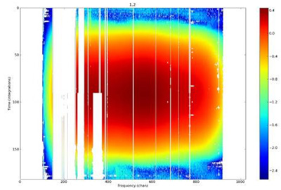
Figure below shows the first radio map of Cassiopea A. It was obtained correlating 32 signals coming from the BEST-2 receivers. Some parts of the radio map are deleted because damaged from strong radio interferences.
 |
|
|
||||||||||
 |
 |
 |
 |
 |
||||||